
Understanding Gear Mod 1: The Metric Key to Pinion and Gear Compatibility
2025-04-22
Getting the right gear components is crucial for any mechanical system, whether it’s a massive industrial machine or a delicate RC car. A key specification you’ll often encounter, especially with metric systems, is the gear module, often abbreviated as "mod". Understanding what mod means, particularly common sizes like Mod 1 or Mod 0.8, is vital for ensuring parts mesh correctly and perform reliably. This post dives deep into the world of gear modulus, explaining its significance, how it compares to other systems like Diametral Pitch (DP), and why getting it right matters for everything from simple pinion drives to complex rack and pinion setups. We’ll explore common questions found in forum discussions and provide insights from a manufacturer’s perspective, helping you make informed decisions for your projects. Reading this article will clarify the concept of gear module, saving you time and potentially costly errors in specification and procurement.
What Exactly Does Gear "Mod" or "Module" Mean?
In the realm of gear engineering, precision is paramount. One of the fundamental parameters defining the size and characteristics of a metric gear tooth is the module (often shortened to mod). So, what does this term actually mean?
The gear module (mod) is a unit defining the size of the gear teeth in millimeters. Specifically, it represents the ratio of the gear’s pitch diameter (an imaginary circle where mating gears effectively touch) to its number of teeth. The formula is quite straightforward:
Module (m) = Pitch Diameter (Pd) / Number of Teeth (N)
Essentially, a larger module number indicates a larger tooth size, and consequently, a stronger gear capable of transmitting more torque. Conversely, a smaller module corresponds to finer, smaller teeth. This metric standard simplifies the design and manufacturing process, ensuring that any two metric gears with the same module and pressure angle will mesh correctly, regardless of their respective number of teeth or diameter. This standardization is a frequent topic in many engineering forum post entries where compatibility is discussed. Understanding the mod is the first step towards ensuring different gear components, like a pinion and its mating gear, will work together seamlessly.
This concept is crucial because it directly relates the gear’s overall size to the size of its individual teeth. When you see a gear specified as "Mod 2," for instance, it tells you immediately about the scale of its teeth compared to a "Mod 1" or "Mod 3" gear. This system provides a clear, standardized way to classify and match metric gears, which is invaluable for designers, manufacturers like us at Xinda Slewing Bearing, and procurement specialists like Mark Thompson who need reliable, interchangeable parts. A frequent query in technical forum threads revolves around identifying the mod of an unknown gear, highlighting its importance in replacement and repair scenarios. This post aims to clarify these fundamental aspects.
Decoding Mod 1: What Does This Specific Number Tell Us?
When you encounter a gear labeled "Mod 1" or "1.0 Mod," what specific information does that convey? It’s a direct indicator of the tooth size according to the metric module system.
A Mod 1 gear signifies that for every tooth on the gear, there is 1 millimeter of pitch diameter. So, using the formula Pitch Diameter = Module * Number of Teeth:
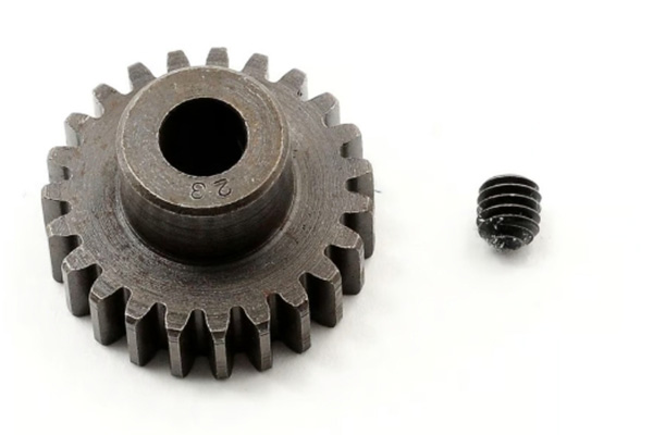
- A Mod 1 gear with 20 teeth (often written as 20T) will have a pitch diameter of 1 mm * 20 = 20 mm.
- A Mod 1 gear with 50 teeth (50T) will have a pitch diameter of 1 mm * 50 = 50 mm.
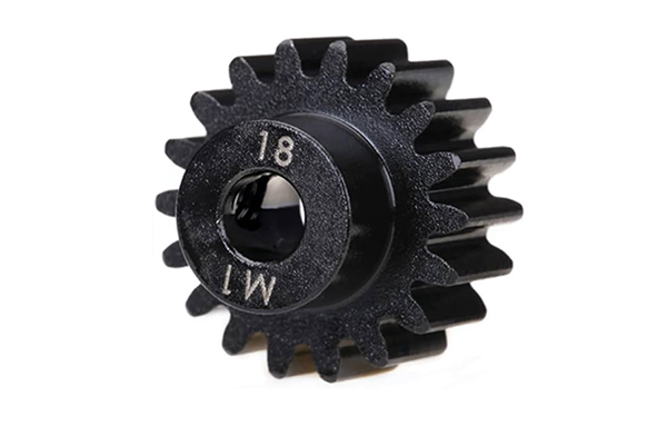
This makes Mod 1 a very convenient reference point in the metric system. It establishes a direct 1:1 relationship between the number of teeth and the pitch diameter in millimeters. Gears with Mod 1 are commonly found in various applications, including hobbyist projects like RC vehicles, robotics, and light-duty machinery where moderate strength and precision are required. It’s a popular choice discussed in many an online forum post comparing different gear sizes.
The significance of "Mod 1" lies in its clear definition of tooth proportions. All Mod 1 gears share the same fundamental tooth size and profile (assuming the same pressure angle, typically 20 degrees). This ensures that any Mod 1 pinion will correctly mesh with any other Mod 1 gear or Mod 1 gear rack. This interchangeability is a major advantage of the module system, simplifying design and part sourcing. Understanding this specific number helps users quickly gauge the size and potential load capacity of the gear. This baseline understanding is crucial before delving into variations like Mod 0.8 or larger mod values. We frequently get questions about specific mod sizes in specification sheets, making this a common thread in technical communication.
Mod vs. Pitch (DP): What’s the Key Difference Between Metric and Imperial Systems?
While the metric world predominantly uses the Module (mod) system, the Imperial system (common in the USA) uses Diametral Pitch (DP). Understanding the difference is crucial, especially for businesses operating internationally or dealing with equipment from different regions. Many a forum post has been dedicated to converting between these systems.
Here’s the fundamental difference:
- Module (mod): As discussed,
Module = Pitch Diameter (mm) / Number of Teeth. A larger module number means larger teeth. It’s a direct measure of size. - Diametral Pitch (DP):
DP = Number of Teeth / Pitch Diameter (inches). A larger DP number means smaller teeth (more teeth per inch of pitch diameter). It’s an inverse measure of size.
Think of it like this: Mod tells you "millimeters per tooth" (on the pitch circle), while DP tells you "teeth per inch" (of pitch diameter). They are essentially inverse concepts scaled by the metric/imperial conversion. A common comparison point often seen in RC hobbies is Mod 0.8 vs 48DP. While numerically close, they are not interchangeable due to the unit difference and calculation base. 48DP means 48 teeth per inch of pitch diameter, whereas Mod 0.8 means each tooth corresponds to 0.8mm of pitch diameter.
Here’s a simple table highlighting the key differences:
| Feature | Module (mod) System | Diametral Pitch (DP) System |
|---|---|---|
| Unit Base | Metric (millimeters) | Imperial (inches) |
| Calculation | Pd (mm) / N |
N / Pd (inches) |
| Size Meaning | Larger Mod = Larger Tooth | Larger DP = Smaller Tooth |
| Common Use | Europe, Asia, Global Std. | Primarily USA |
It’s vital not to mix Mod and DP gears. They won’t mesh correctly due to the fundamental difference in tooth geometry and spacing, leading to rapid wear, noise, and system failure. When specifying or ordering parts, always ensure you’re consistently using either the metric module or the imperial DP system based on your project requirements or existing equipment standards. This clarification should address many points raised in technical post entries online.
How Do You Calculate Gear Dimensions Using the Module System?
The beauty of the gear module (mod) system lies in its simplicity for calculating key gear dimensions. Once you know the module and the number of teeth (N), you can easily get other critical parameters. This is often a practical point discussed in detail within technical forum threads.
Here are the fundamental calculations based on the module (m):
-
Pitch Diameter (Pd): This is the most basic calculation. As defined earlier:
Pd = m * N
Example: For a Mod 1.5 gear with 30 teeth, Pd = 1.5 mm * 30 = 45 mm. -
Outside Diameter (OD): This is the overall diameter of the gear, measured across the tips of the teeth. For a standard spur gear:
OD = m * (N + 2)
Example: For the same Mod 1.5, 30T gear, OD = 1.5 mm (30 + 2) = 1.5 mm 32 = 48 mm. -
Tooth Depth (h): The total height of a tooth. For standard gears, it’s typically:
h = 2.25 * m(This includes clearance)
Example: For a Mod 1.5 gear, h = 2.25 * 1.5 mm = 3.375 mm. -
Center Distance (a): When meshing two external gears (e.g., a pinion and a gear), the distance between their centers is crucial.
a = (Pd1 + Pd2) / 2 = m * (N1 + N2) / 2
Example: Meshing a Mod 1.5, 20T pinion with a Mod 1.5, 40T gear:a = 1.5 * (20 + 40) / 2 = 1.5 * 60 / 2 = 45 mm.
These formulas provide the essential dimensions needed for designing gear trains, selecting appropriate bearings like our Precision double-row ball slewing ring, and ensuring proper mounting and operation. The ease of these calculations, derived directly from the module and tooth count, is a significant advantage of the metric system. Remember to consistently use millimeters when working with module. This systematic approach reduces errors and simplifies the design process, a benefit frequently highlighted in technical post comparisons.
Common Questions Answered: Insights from Online Forums and Posts
Online forum platforms and discussion thread boards are invaluable resources for understanding the practical challenges and questions users face regarding gear module (mod). Many a post reflects recurring themes and points of confusion. Let’s address some frequently asked questions:
-
"Can I use a Mod 0.8 pinion with a 48DP gear?"
No. As explained earlier, Mod (metric) and DP (imperial) define tooth geometry differently. Mod 0.8 and 48DP teeth are similarly sized but not identical in profile or spacing. Attempting to mesh them will lead to poor contact, excessive wear, and likely failure. This is a very common thread in RC car forums. -
"How do I find the module of an existing gear?"
If the gear isn’t marked, you can estimate the module. Measure the Outside Diameter (OD) in millimeters and count the Number of Teeth (N). Then, use the rearranged OD formula:m ≈ OD / (N + 2). The result should be close to a standard module value (e.g., 0.5, 0.8, 1, 1.25, 1.5, 2, etc.). Precise measurement requires proper metrology tools. This question pops up constantly in "Identify this part" post types. -
"Is a higher module always better?"
Not necessarily. Higher module means larger, stronger teeth, suitable for higher torque. However, it also means a larger, heavier gear with potentially less precision and more backlash (play between meshing teeth) for a given diameter. The choice depends on the application’s specific requirements for strength, size, weight, precision, and speed. This trade-off is a frequent discussion point in design forum posts. -
"What does the pressure angle (e.g., 20°) mean with module?"
The pressure angle defines the angle at which force is transferred between meshing teeth. Gears must have both the same module and the same pressure angle to mesh correctly. 20° is the most common standard today, but 14.5° exists in older systems. Mixing pressure angles is another incompatibility issue highlighted in technical post warnings.
Understanding these common queries, often found scattered across numerous forum post entries and threads, helps clarify the practical application and potential pitfalls of working with the gear module system.
Why is Pinion Mod Size So Important for Gear Ratio and Strength?
The pinion is typically the smaller of two meshing gears, often the driving gear connected to a motor or input shaft. The choice of pinion module (mod) has significant implications for both the gear ratio and the overall strength of the drive system.
Firstly, the module directly influences the physical size of the pinion. For a given number of teeth, a larger module results in a larger pinion diameter. This impacts the achievable gear ratio within a specific space constraint. The gear ratio is determined by the ratio of the number of teeth on the gear (N_gear) to the number of teeth on the pinion (N_pinion): Ratio = N_gear / N_pinion. While the module itself doesn’t appear in the final ratio calculation (as it cancels out if both gears share the same mod), it dictates the minimum and maximum pinion size (and thus tooth count) that can fit, indirectly affecting the range of achievable ratios.
Secondly, and often more critically, the module is a primary determinant of tooth strength. Larger teeth (higher mod) can withstand significantly higher loads and torque before breaking or wearing excessively. When designing a drive, especially for demanding applications, selecting an appropriate module for the pinion (and mating gear) is crucial to ensure longevity and prevent catastrophic failure. Using too small a module for the required load is a common design error discussed in engineering failure analysis post examples. The pinion, often having fewer teeth engaging simultaneously, can be particularly vulnerable, making its mod selection critical. Choosing a robust pinion ensures the reliability of the entire gear set.
How Does Modulus Apply to Rack and Pinion Gear Systems?
Rack and pinion systems convert rotational motion into linear motion or vice versa. They consist of a circular gear (the pinion) meshing with a linear gear bar (the rack). The gear modulus (mod) plays the same fundamental role here as it does with two circular gears: it defines the tooth size and ensures compatibility.
For a rack and pinion system to function correctly, both the rack and the pinion must have the same module and pressure angle. The module dictates the size, profile, and spacing of the teeth on both components. If the modulus values differ, the pinion teeth will not mesh properly with the rack teeth, leading to jamming, excessive wear, and failure to translate motion smoothly.
The module also influences the linear distance traveled by the rack for one revolution of the pinion. This linear travel distance (L) is equal to the pitch circumference of the pinion:
L = π * Pd = π * m * N_pinion
Where m is the module, N_pinion is the number of teeth on the pinion, and Pd is the pinion’s pitch diameter. Therefore, for a given pinion tooth count, a larger module will result in greater linear movement per revolution. This calculation is essential for applications requiring precise linear positioning, such as CNC machines or steering systems. Choosing the correct modulus is critical for the performance and accuracy of any rack and pinion mechanism, a point often emphasized in automation forum post discussions.
Choosing Wisely: Selecting the Right Mod for Your Application (Incl. Mod 0.8)
Selecting the appropriate gear module (mod) is a critical design decision that balances several factors: load capacity, precision, size, weight, cost, and available space. There’s no single "best" mod; the optimal choice depends entirely on the specific application.
- Load & Strength: Higher torque applications demand larger teeth for adequate strength. This points towards choosing a higher module (e.g., Mod 1.5, 2, 3, or even larger for heavy industrial use). Smaller modules (Mod 1 or less) are suitable for lighter loads.
- Precision & Speed: Smaller module gears often offer finer control and potentially smoother operation at high speeds, assuming high manufacturing accuracy. They are common in instrumentation, robotics, and small mechanisms. Larger teeth might introduce more vibration or noise at very high speeds.
- Size & Weight: Larger module gears are inherently bigger and heavier for a given ratio. If space or weight is a constraint (e.g., aerospace, portable devices, RC models), a smaller module might be necessary, potentially requiring stronger materials or wider gears to compensate for the reduced tooth size.
- Mod 0.8: This specific module, Mod 0.8, is very popular in the radio-controlled (RC) hobby world, particularly for electric motor pinions (both brushed and brushless) in 1/10th and 1/8th scale vehicles. It offers a good balance between tooth strength for powerful brushless systems and relatively fine control, often compared favorably against the imperial 48DP standard in RC forum posts. It’s a step up in durability from even smaller modules like Mod 0.5 or 0.6 used in smaller scale models.
- Availability & Cost: Common standard module sizes (Mod 1, 1.5, 2, etc.) are generally more readily available and cost-effective than non-standard or very large/small modules.
Making the right choice involves analyzing the operational forces, speed requirements, space constraints, and desired lifespan. Consulting gear manufacturer catalogs and potentially discussing requirements in a relevant technical forum thread can provide valuable guidance. As manufacturers of components like Ball Slewing Bearings that often incorporate gears, we understand the importance of matching the gear specifications, including the mod, to the application’s demands. This detailed selection process is a recurring thread in engineering design discussions.
The Compatibility Question: Can You Mix Different Mod Gears?
This question comes up surprisingly often, usually driven by attempts to make existing parts work or due to ordering mistakes. The answer is unequivocally no. You absolutely cannot mesh gears with different module (mod) values and expect them to work correctly or reliably.
The gear module defines the fundamental size and spacing of the gear teeth. Even a small difference in module between two mating gears means their teeth profiles and spacing won’t align properly. Trying to force them to mesh will result in:
- Point Contact: Instead of smooth rolling contact along the tooth flank, the teeth will likely contact only at specific points or edges.
- Excessive Wear: This point contact creates extremely high localized pressure, leading to rapid wear and abrasion of the tooth surfaces.
- Binding and Jamming: The mismatched profiles can cause the gears to bind or jam, potentially stalling the motor or causing mechanical failure.
- Increased Noise: Improper meshing generates significant noise and vibration.
- Reduced Strength & Failure: The drive will be significantly weakened, unable to transmit the intended torque, and prone to premature tooth breakage.
This applies not just to different module numbers (e.g., trying to mesh a Mod 1 gear with a Mod 1.25 gear) but also to mixing metric module gears with imperial DP gears (like the Mod 0.8 vs 48DP example). They are fundamentally incompatible systems. Always ensure that mating gears share the exact same module and pressure angle. This rule is a cornerstone of gear design and a frequent topic in troubleshooting post entries on technical forums. Any attempt to circumvent this leads to problems.
From a Manufacturer’s View: Why Precision Mod Matters
As a factory specializing in components like slewing ring bearings which often incorporate integral gearing (slewing gear), precision in manufacturing the gear module (mod) is non-negotiable. For Mark Thompson and other procurement officers relying on consistent quality, understanding why this precision is vital builds confidence in the supplier.
The specified module dictates the exact dimensions and profile of each gear tooth. Even minor deviations from the nominal mod value, or inconsistencies across the gear, can lead to significant operational problems:
- Uneven Load Distribution: If tooth spacing varies due to mod inaccuracies, some teeth will carry more load than others, leading to localized stress and premature failure.
- Increased Backlash or Binding: Inaccurate mod affects the fit between mating teeth. Too much deviation can cause excessive backlash (sloppiness) or binding (tightness), impacting positional accuracy and efficiency.
- Noise and Vibration: Manufacturing inconsistencies related to the mod are a primary source of gear noise and vibration, indicating inefficient power transmission and potential wear issues.
- Reduced Lifespan: Ultimately, a lack of precision in adhering to the specified module compromises the strength, smoothness, and lifespan of the gear system.
Achieving high precision requires sophisticated gear cutting or hobbing machinery, stringent quality control processes, and careful material selection. Verifying the module and overall gear geometry using specialized metrology equipment is a standard part of our quality assurance. When customers specify a gear with a particular mod, they need assurance that the manufactured part adheres strictly to that standard for reliable performance. This commitment to precision is a frequent assurance provided in our technical communication and documentation, often preempting questions that might otherwise appear in a support thread or post.
Troubleshooting: Common Mod Mismatch Issues and How to Fix Them
Despite the clear rule about matching module (mod) values, mismatch issues still occur, often due to misidentification, incorrect ordering, or attempts to integrate components from different systems. Recognizing the symptoms and knowing the fix is crucial. This often becomes a troubleshooting thread in technical help forums.
Symptoms of Mod Mismatch:
- Gears Won’t Mesh: The most obvious sign – the teeth simply don’t fit together smoothly.
- Grinding Noise: If forced to turn, mismatched gears will produce loud grinding or clicking noises.
- Excessive Heat: Friction from improper contact generates heat.
- Binding/Stalling: The drive may seize up or stall the motor.
- Rapid Wear: Visible and accelerated wear patterns on the tooth faces.
- Broken Teeth: Eventually, the incorrect loading will likely shear off gear teeth.
The Fix:
Unfortunately, there’s only one reliable solution: Replace one or both components so that the mating gears (or rack and pinion) have the exact same module and pressure angle.
- Identification: Correctly identify the required module for your system. If unsure, measure an existing, known-good component using the
m ≈ OD / (N + 2)estimation or consult the equipment documentation. Many a helpful forum post guides users through this identification. - Sourcing: Order replacement parts specifically matching the required module (Mod 1, Mod 0.8, etc.) and pressure angle (usually 20°). Double-check specifications before ordering.
- Verification: When parts arrive, visually inspect the tooth size and, if possible, compare them against a known-good sample or specification sheet.
Trying to modify mismatched gears (e.g., filing teeth) is generally not feasible or advisable, as it destroys the precise tooth profile needed for proper power transmission. The only reliable result comes from using correctly matched gear components based on their specified module. This straightforward fix, though sometimes inconvenient, prevents much larger problems down the line, a point reiterated in countless technical support post replies.
Key Takeaways on Gear Module (Mod)
To ensure smooth operation, compatibility, and longevity in your geared systems, remember these key points about gear module (mod):
- Definition: Module (mod) is the metric measure defining gear tooth size (
Module = Pitch Diameter / Number of Teeth). - Size Relationship: Larger module number = larger tooth = higher strength.
- Compatibility: Mating metric gears must have the exact same module (e.g., Mod 1 with Mod 1, Mod 0.8 with Mod 0.8) and pressure angle (usually 20°) to mesh correctly.
- Mod vs. DP: Module is metric (mm/tooth); Diametral Pitch (DP) is imperial (teeth/inch). They are not interchangeable. Higher DP = smaller tooth.
- Calculation: Key dimensions (Pitch Diameter, Outside Diameter, Center Distance) are easily calculated using the module and number of teeth.
- Pinions & Racks: The module dictates pinion size/strength and the linear travel in rack and pinion systems. Both components must share the same modulus.
- Selection: Choose the module based on application requirements: load, precision, speed, size, and weight. Common sizes like Mod 1 and Mod 0.8 serve different typical applications.
- Precision: Accurate manufacturing to the specified module is critical for performance and lifespan, a key focus for quality suppliers. Any technical post on gear failure will highlight this.
- Troubleshooting: Mismatched mod leads to noise, wear, binding, and failure. The only fix is to use correctly matched components.
Understanding and correctly applying the gear module concept is fundamental for anyone working with metric gears. It ensures compatibility, simplifies design, and leads to more reliable and efficient mechanical systems. Don’t hesitate to consult specifications or reach out to knowledgeable suppliers if you have doubts – getting the mod right from the start saves significant trouble later.